Project
Power Module
24V battery pack with ORed ground power input, buck conversion to 3.3V and 5V, and hardware lockout for flight avionics.
The Problem
Solenoids pull hard on the power rail. If the avionics share that rail without isolation, a solenoid firing can brown out the flight computer mid-flight. A single power reset during a burn is mission over.
What I built
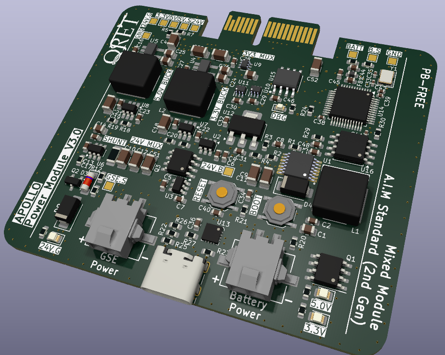
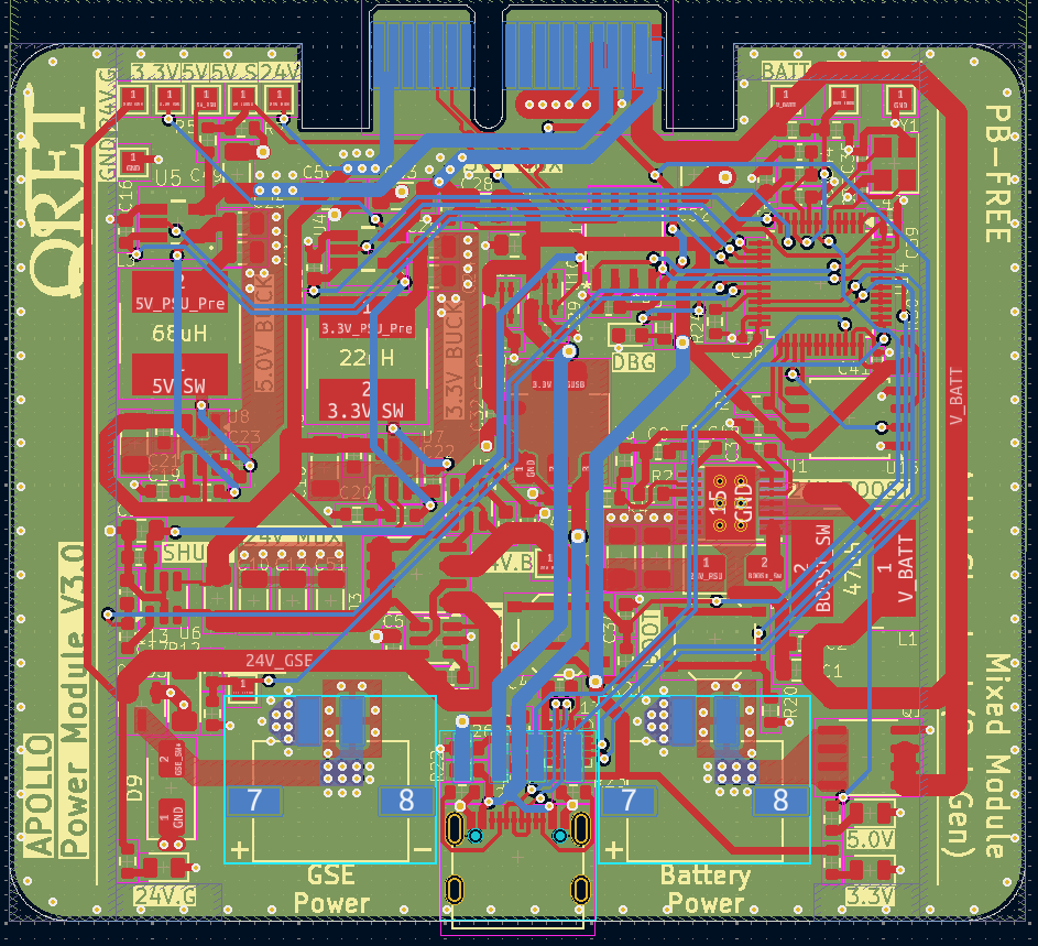
The power module ORs two 24V sources: one from an external ground supply (used during oxidizer fill) and one from a boost converter off the 18650 battery pack. Since our total wattage is low, I kept the design simple — just two buck converters with a single 24V input producing 3.3V and 5V rails. No battery charger on board; we rely on pre-charged cells and ground power to get us through the fill phase.
All the inductor and capacitor sizing was calculated to keep the converters in CCM during normal operation. High current draw really only happens during launch, and that's brief.
Highlights
- ORed 24V input from ground power and battery boost converter.
- Inductor/capacitor sizing for Lcrit — CCM maintained under regular operating current.
- PMOSFET reverse polarity protection on the ground power input with zener shunt for Vgs clamping.
- Found a bug during bring-up: no current limiting resistor in the zener shunt path. Above 12V the shunt was sinking too much current and overheating. Added the resistor in rework, fixed it.
- Systematic board bring-up — probed all rails for continuity, checked resistance to ground, current-limited power supply for first power-on.
Media
3D Viewer
Drag to rotate, scroll to zoom.